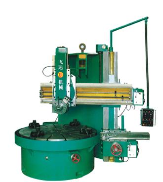
 The drive connection on the machine tool, whether it is the internal contact drive or the external contact drive, can be realized not only by the mechanical transmission of the rigid body transmission part, but also by the non-mechanical transmission method according to the nature of the movement, such as hydraulic, electrical, Pneumatic, light and heat. With the rapid development of microelectronics technology, the current way of controlling movements and achieving transmission linkages by computers or electronic hardware is getting more and more applications.
 The use of non-mechanical means of driving linkage can simplify the mechanism, shorten the transmission chain, and facilitate the realization of automatic control. However, for the composite table that requires high transmission accuracy and the formation of the motion transmission chain, such as the generative movement of the gear processing machine and the indexing movement transmission chain, there are still few hydraulic, electrical, and pneumatic methods used to realize the internal linkage transmission of the movement. For the drive chains with simple surface forming motions that do not require high drive accuracy, such as the lathes, milling machines, etc., the cutting speed and the drive of the feed drive are more commonly used in hydraulic, electrical, and pneumatic methods to achieve the transmission linkage. .
The machine tool transmission system: The graphic symbols represent the various transmission parts in the mechanical transmission system of the real machine tool, and the integrated schematic drawing of the machine tool transmission chain is called the machine tool transmission system diagram, which is referred to as the machine transmission system. This diagram concisely represents the internal structure of the machine tool and the various transmission chains, and is a powerful tool for analyzing the transmission law of the machine tool. Familiar with the transmission system diagram, it is very important for the dump and research machine tools. With the transmission system diagram, the performance, working principle and application range of the machine tool can be analyzed, and various adjustment calculations can be performed. Representative drawings and symbols of various transmission parts of the machine tool have been listed in the national standard (see the national standard GB/T4460--84 mechanical drawing diagram of a mechanism movement diagram).
Frp Pipe,Grp Pipe,Frp Tube,Grp Pipe Fittings
Hebei Chunfeng International Trade Co., Ltd , https://www.chunfengenergy.com